🚧 This site is actively being updated. Some sections are still in progress. 🚧
PROJECT 01
APEX
Autonomous Precision Exploration
ROS 2
Raspberry Pi 5
RP2040
3D Printed
Overview
What is APEX?
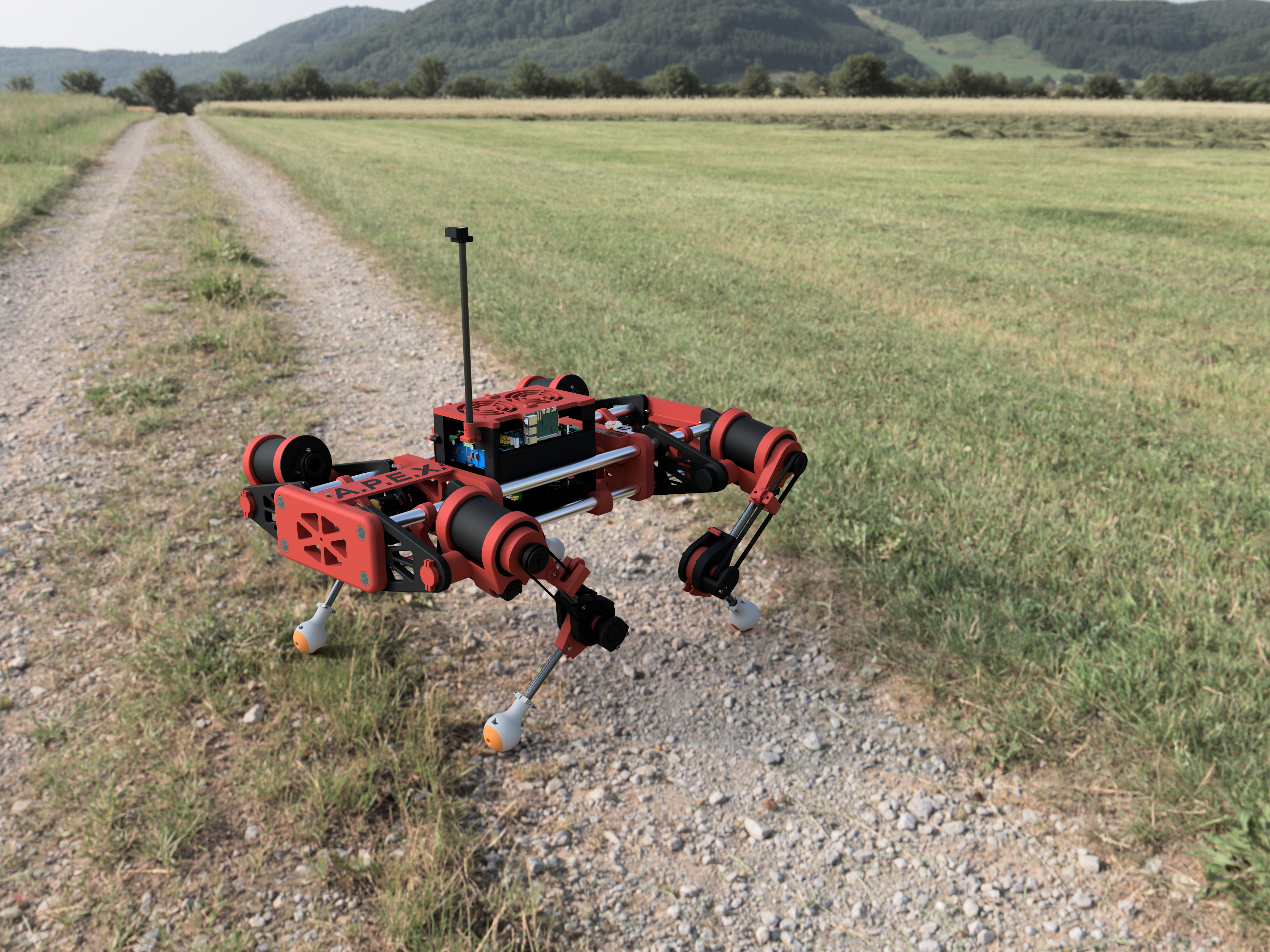
APEX is a fully custom quadruped robot built from the ground up — frame, electronics, firmware, and software stack. Runs ROS 2 on a Raspberry Pi 5 as the main compute unit, with four dedicated RP2040 microcontrollers handling per-leg PID control at low latency. Built as a capable autonomous platform for navigating uneven terrain with an eventual sensor payload.
Key Components
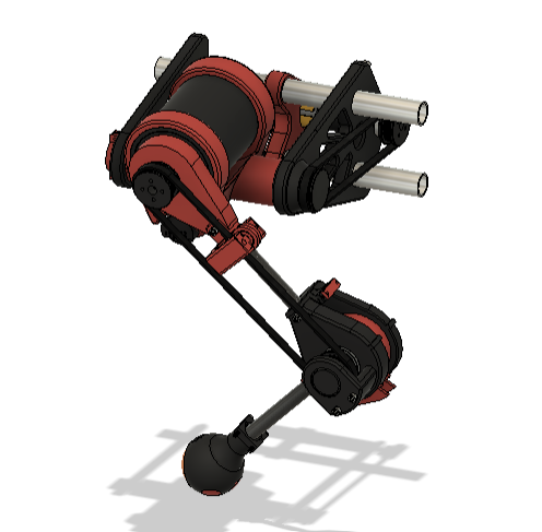
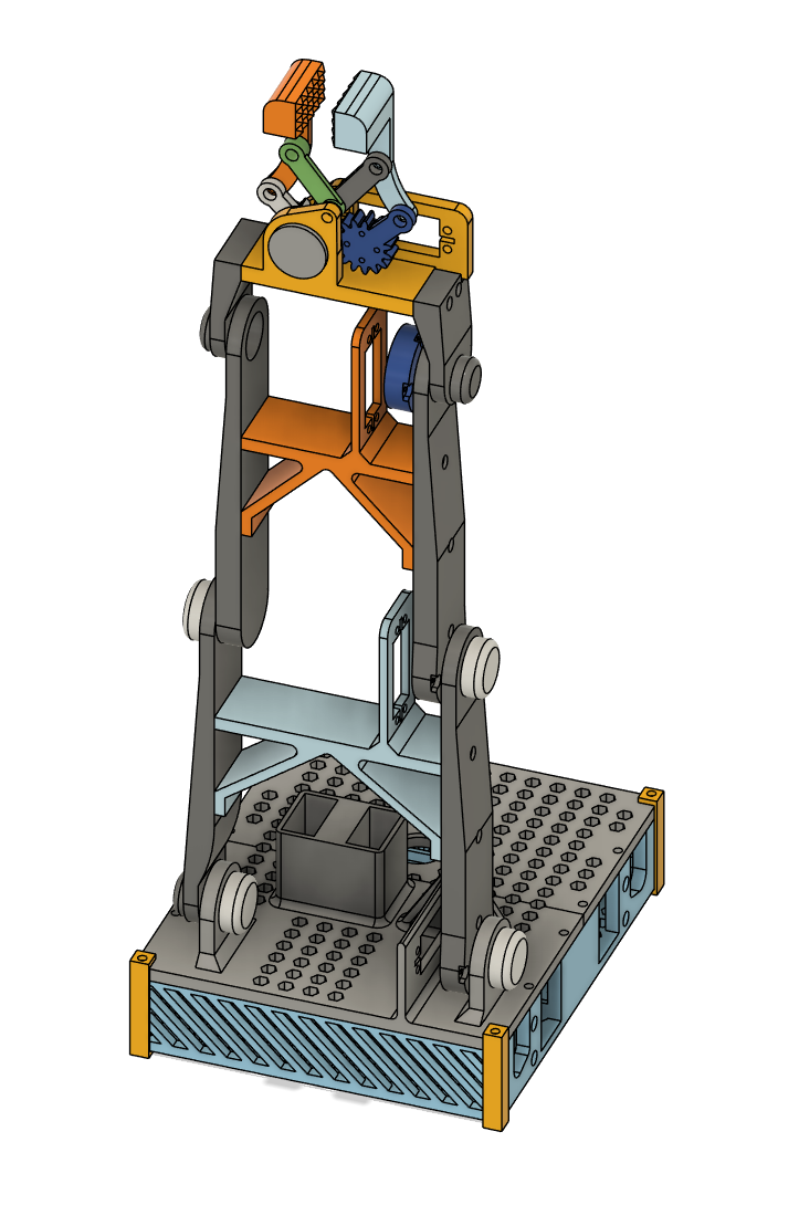
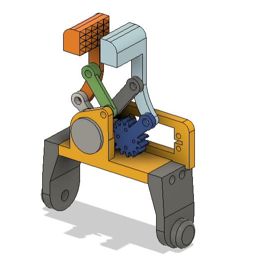
3 DOF High-Torque Legs
Each of APEX's four legs has three independently controlled joints — hip roll, hip pitch, and knee — giving the robot twelve degrees of freedom in total. Every joint is driven by a GoBilda planetary gear motor with a 99.5:1 reduction ratio, delivering high torque at low speed for precise, powerful movement across uneven terrain.
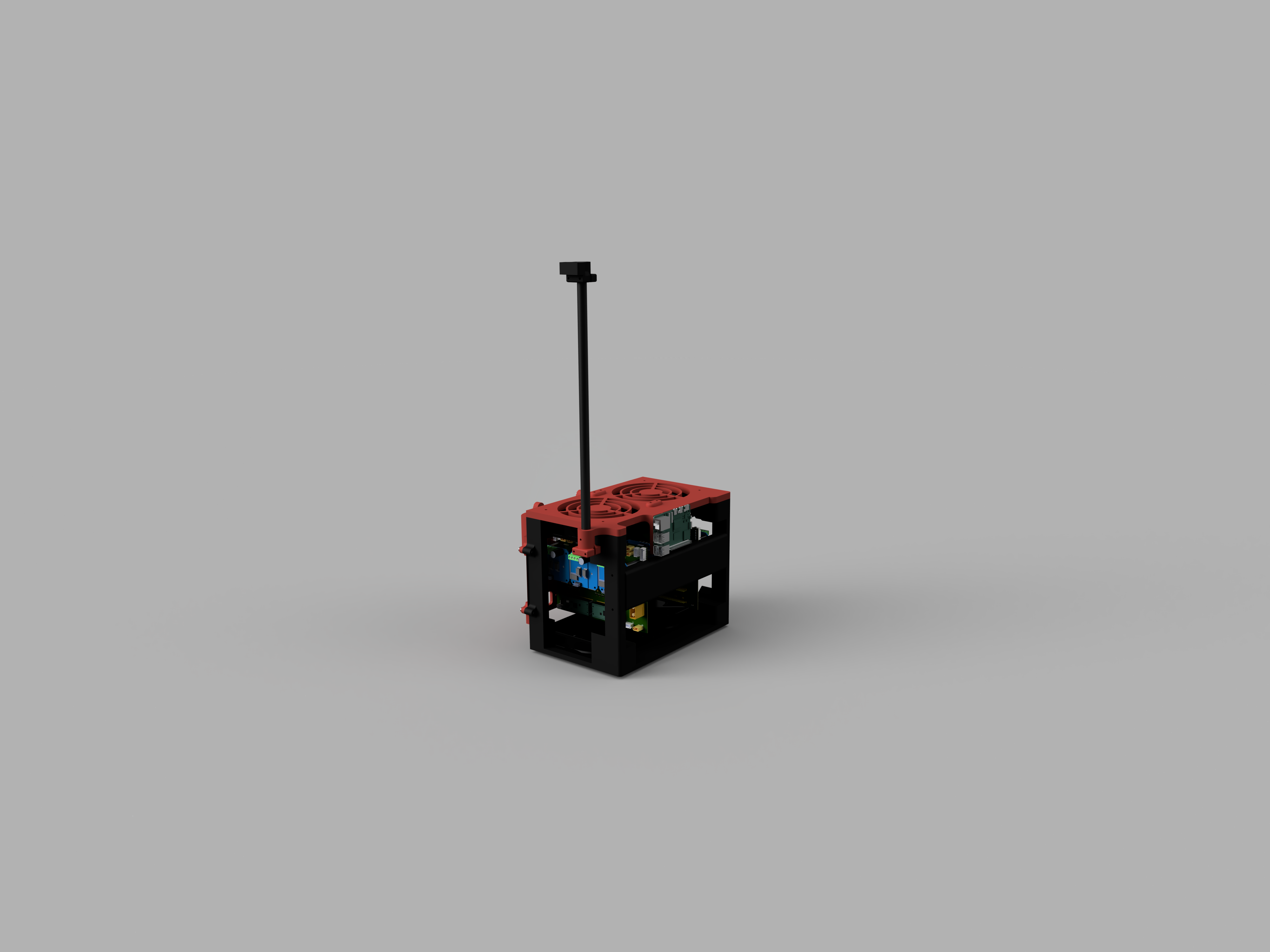
Custom PCB & Enclosure
Rather than a tangle of wires and breadboards, APEX uses a custom-designed PCB to manage power distribution and signal routing across all twelve motor controllers. The board is designed to handle the high current demands of running twelve motors simultaneously while keeping the electronics compact and reliable. Additionally, the dual boards are housed in an enclosure designed for optimal portability, modularity, simplicity, and functionality.
Open-Source Code Repository
All of APEX's software is publicly available on GitHub. The full codebase covers inverse kinematics, gait generation, PID motor control, IMU stabilization, GPS navigation, and live camera streaming. The CAD will be published once the build is complete. The goal is for APEX to be a real reference that other students can actually build on without starting from zero.

ROS 2
APEX runs on ROS 2, using its publish-subscribe architecture to handle communication between the robot's major systems. Navigation commands, joint targets, and operating mode changes are all passed between nodes over typed topics, keeping each subsystem decoupled and independently manageable. A multi-threaded executor runs the controller and stream server nodes in parallel, allowing the gait loop, camera stream, and telemetry monitoring to all operate concurrently without blocking each other. Using ROS 2 also sets the foundation for future expansion — adding new sensors, a SLAM module, or an ML-based perception node becomes a matter of writing a new node and connecting it to the existing topic graph rather than rewiring the entire codebase.
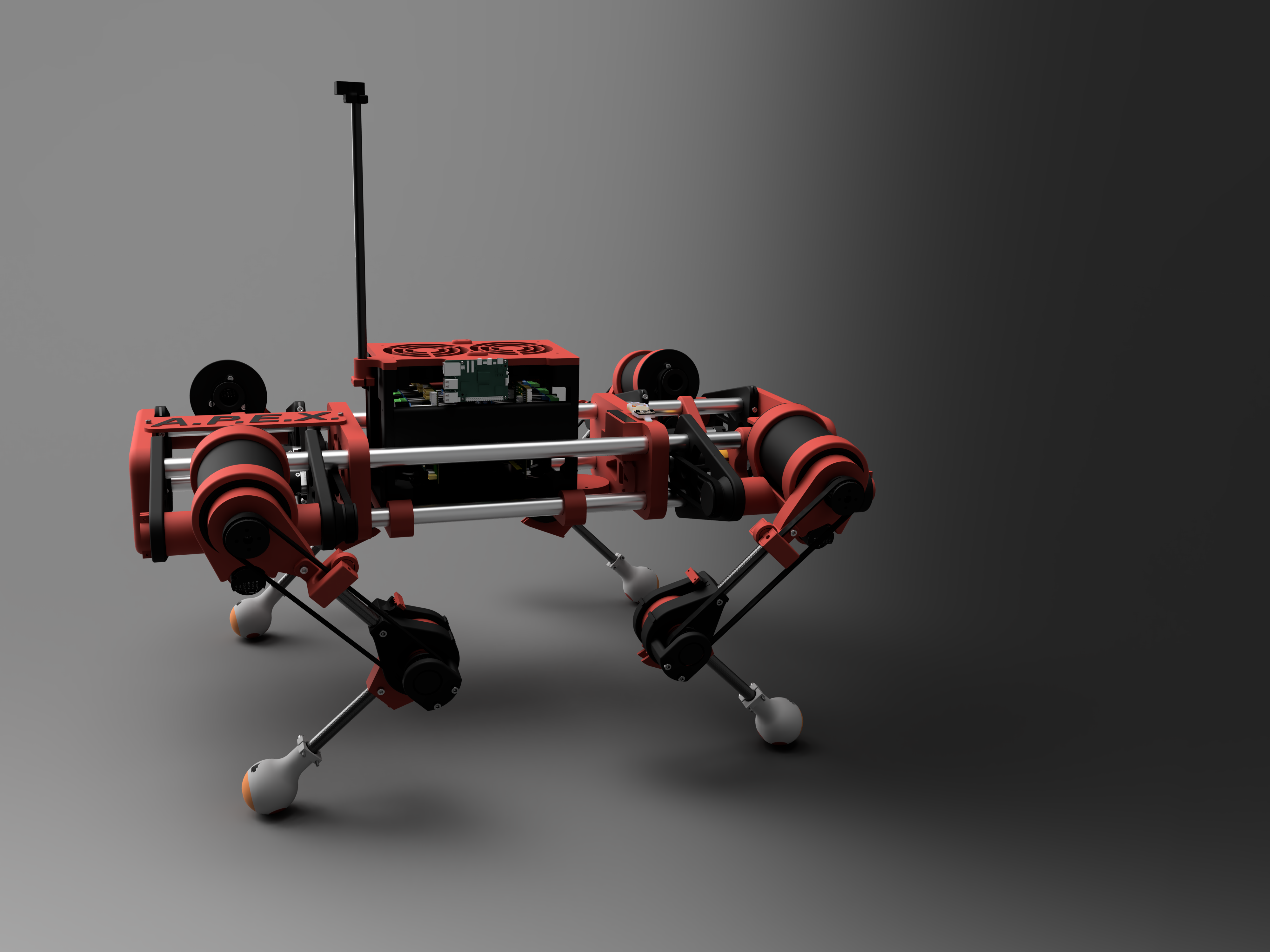
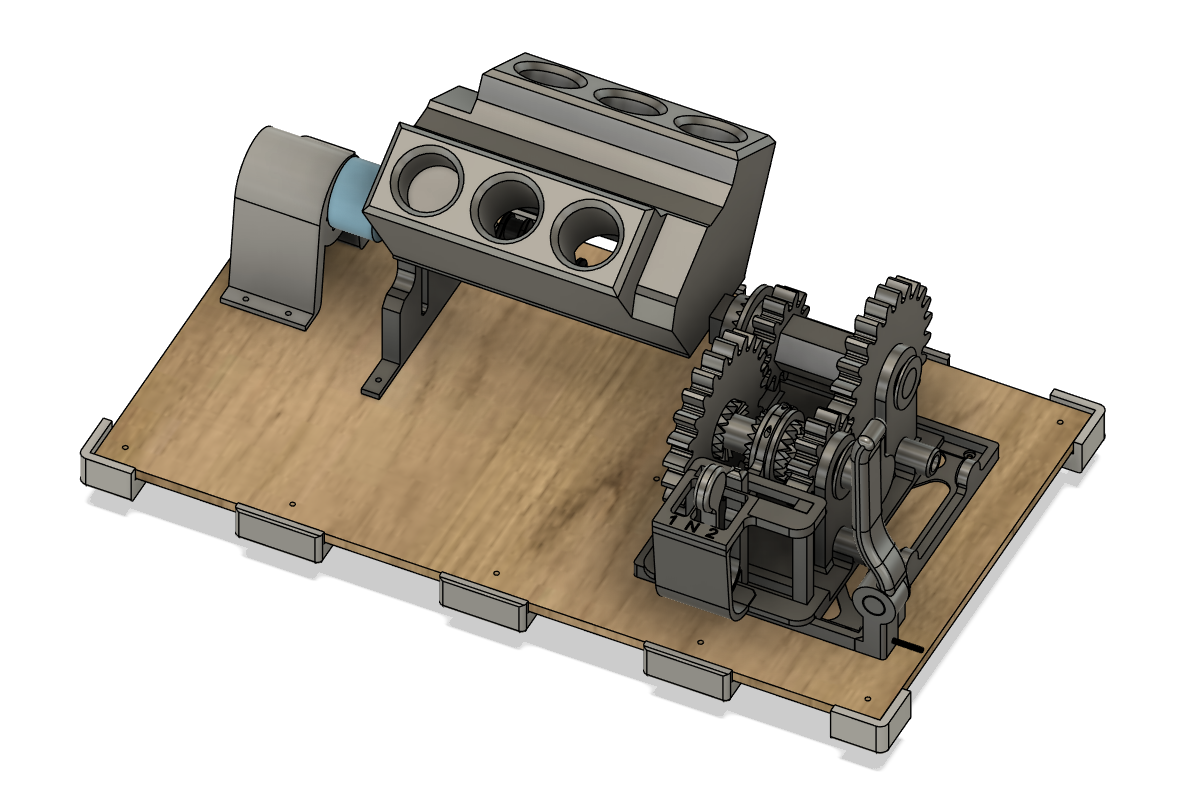
3D Printed Chassis
The majority of APEX's structural components are 3D printed in carbon fiber reinforced PETG, chosen for its combination of stiffness, impact resistance, and printability. The parts were designed specifically for FDM manufacturing, with wall thicknesses, infill, and orientations optimized for the load paths each component experiences during walking.
[ Battery / Power Photo ]
Power System
Main power: LiperiAir 5000mAh 3S 80C LiPo. Logic power: Liperior 3500mAh 2S 25C LiHV. Charged with a Gens Ace D300 dual-channel charger.
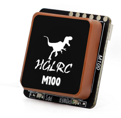
GPS-based Guidance
In autonomous mode, APEX uses a HGLRC M100 GPS module and an onboard compass to navigate to real-world waypoints. The navigation system computes a bearing from the robot's current coordinates to the target, calculates the heading error, and feeds a turn command into the gait controller to steer the robot in the right direction. It is the foundation for the fully autonomous outdoor navigation planned for future development.
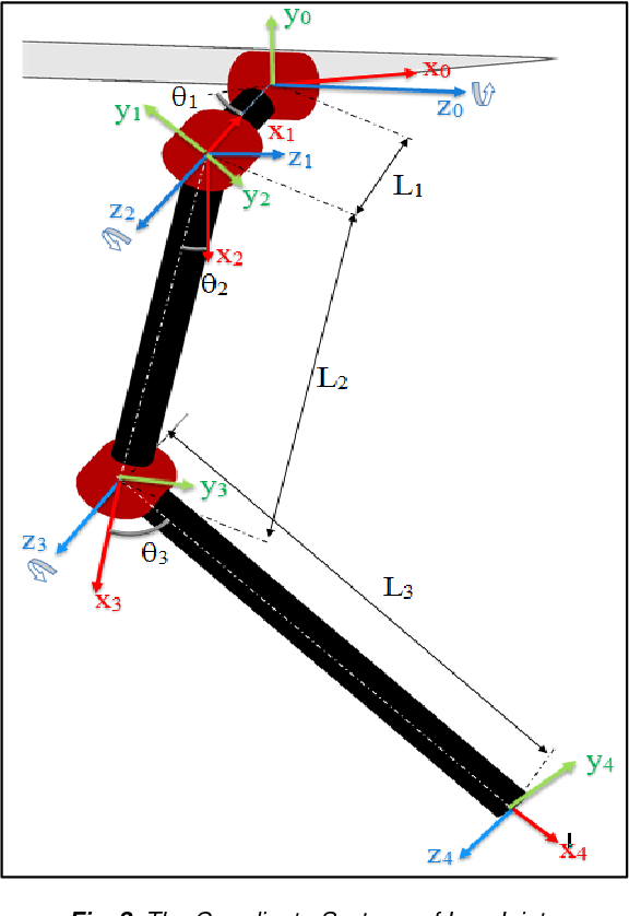
Inverse Kinematics
Rather than manually specifying motor angles, APEX uses a custom inverse kinematics engine to compute the correct joint angles for any given foot position in 3D space. Given a target X, Y, Z coordinate for the foot, the IK solver works backwards through the leg geometry to find the exact roll, pitch, and knee angles needed to put the foot there. This runs in real time across all four legs on every step, and is what makes smooth, adaptable walking possible.